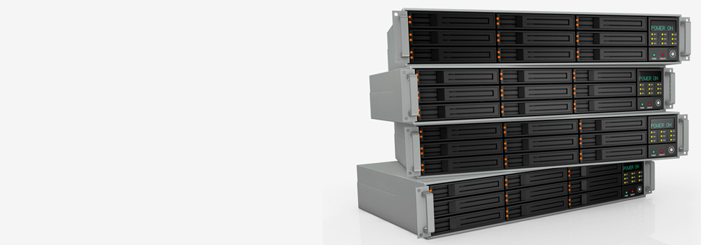

Maidenhead Data Recovery – No.1 NAS and RAID Data Recovery Specialists
Maidenhead Data Recovery is a leading RAID data recovery provider with over 25 years of expertise. We specialize in RAID 0, 1, 5, 10 and all other RAID levels, serving everyone from home users and small businesses to large enterprises and government departments. Contact our RAID engineers today for a free diagnostic – we offer the best value in the UK and have a proven track record recovering data from all types of complex RAID failures.
Our team has successfully completed RAID recoveries for home NAS units, multi-disk servers, large multi-national companies’ storage arrays, and everything in between. We handle both consumer NAS drives and enterprise rack servers, tailoring our approach for each case. All major RAID hardware and software platforms are supported, including software RAIDs, hardware RAID controllers, NAS devices, large NAS cabinets, and rack-mounted RAID systems. We work with all popular RAID brands – from consumer NAS brands like Synology and QNAP to enterprise storage systems by Dell and HPE. Our lab is equipped to treat drive hardware failures (cleanroom repairs) as well as complex logical issues, ensuring the highest chance of full data recovery.
Top 15 NAS Drive Brands (UK) and Their Popular Models
Network-Attached Storage (NAS) devices are common in homes and small offices for data backup and sharing. We recover data from all major NAS external drive brands. Below are the top 15 selling NAS brands in the UK and examples of their popular models:
-
Synology: A market leader known for DiskStation NAS systems. Popular models include the Synology DiskStation DS1522+ and DS923+ (powerful 5-bay systems) and the budget-friendly DS223j. Synology’s NAS units are praised for their user-friendly DSM software and reliability.
-
QNAP: Another top NAS brand offering a wide range of models with robust features. Examples are the QNAP TS-464 4-bay NAS and high-performance units like the TVS-h674T for multimedia applications. QNAP’s NAS lineup (e.g. HS-264 for media streaming) emphasizes powerful hardware options and HDMI multimedia support.
-
Western Digital (WD): Well-known for the My Cloud series of NAS drives. Popular models include the WD My Cloud EX2 Ultra (2-bay prosumer NAS) and the My Cloud PR4100 (4-bay NAS for creative professionals). Higher-end WD NAS products provide capable personal cloud storage.
-
Asustor: A subsidiary of ASUS focusing on NAS. Notable models include the Asustor Nimbustor 2 Gen2 (AS5202T) – a 2-bay NAS with 2.5 GbE ports – which is often cited as a strong alternative to Synology for home users. Asustor NAS devices combine multimedia-friendly hardware with a growing app ecosystem.
-
TerraMaster: An emerging NAS brand offering affordable yet high-performance units. The TerraMaster F4-423 (4-bay) and F5-422 (5-bay) are popular for SMBs, featuring multi-Gigabit LAN and even full-SSD options. TerraMaster NAS units are frequently recommended for their balance of cost and capabilities.
-
Buffalo: Maker of the LinkStation and TeraStation NAS series. For example, the Buffalo TeraStation 3420DN (4-bay desktop NAS) is popular with small businesses, and Buffalo offers rackmount TeraStation models for enterprise. Buffalo NAS devices are valued for their solid hardware and integrated backup features.
-
Netgear: Known for the ReadyNAS product line. Models like the Netgear ReadyNAS RN424 (4-bay) or rackmount ReadyNAS 4312 are used in many offices. Netgear’s NAS solutions focus on easy setup and robust RAID support, making them viable alternatives to Synology/QNAP.
-
Drobo: Known for ease-of-use and BeyondRAID technology. The Drobo 5N2 (5-bay NAS) was a popular home-office NAS, and the Drobo B810n an 8-bay for SMBs. (Note: Drobo’s product lineup hasn’t seen recent updates, but many are still in use.) Drobo devices simplify storage expansion and redundancy for non-technical users.
-
Seagate: Primarily a drive manufacturer, Seagate has offered NAS units like the older Seagate BlackArmor NAS series and Business Storage NAS. They also produce NAS-specific hard drives (IronWolf series) for use in other enclosures. While Seagate’s own NAS devices are fewer today, their drives power many other NAS brands.
-
LaCie: A Seagate subsidiary known for stylish storage geared to creatives. LaCie’s NAS offerings include the LaCie 2big NAS and 5big Network drives. These devices often feature RAID 0/1/5 in desktop enclosures with high capacities, popular for multimedia professionals who need network storage with fast throughput.
-
Thecus: A brand offering NAS solutions for advanced users. Models like the Thecus N4810 (4-bay) or Thecus N12910 (12-bay rackmount) provide robust hardware and support for multiple RAID levels. Thecus NAS systems are favored by some enthusiasts for their balance of cost and enterprise-grade features.
-
LenovoEMC (Iomega): Lenovo’s NAS line (born from Iomega’s StorCenter products) has included models like the Lenovo Iomega ix4-300d (4-bay) and Lenovo EZ Media personal cloud. These NAS devices, though older, were common in many UK small offices. We continue to encounter and recover data from legacy Lenovo/Iomega StorCenter NAS units.
-
Zyxel: Better known for networking gear, Zyxel produced consumer NAS units such as the Zyxel NAS540 (4-bay) and earlier NSA series. These budget-friendly NAS drives offered basic RAID 1/5 capabilities for home users. We have experience retrieving data from Zyxel NAS boxes that have suffered drive failures or firmware issues.
-
Ugreen: A newer entrant in the NAS market, Ugreen has released high-performance NAS like the Ugreen NASync DXP6800 (6-bay NAS with Intel i3 CPU). Ugreen’s NAS devices feature modern hardware (10GbE networking, NVMe slots) and aim at advanced home and SMB users. As these gain popularity, we’re fully equipped to handle data recovery from them as well.
-
HPE (Hewlett Packard Enterprise) MicroServer: While not a traditional NAS appliance brand, HPE’s ProLiant MicroServer line (e.g. MicroServer Gen10 Plus) is often used as a DIY NAS by tech-savvy users. These compact servers support RAID and run custom NAS software (Windows, TrueNAS, etc.). We frequently recover data from such setups, treating them similarly to standard NAS systems.
(Note: We support all NAS and DAS brands – the above are just some of the most common in the UK market. Whether you use a desktop NAS or a direct-attached RAID enclosure, our team can recover the data.)
Top 15 RAID Rack Server Brands and Models
For enterprise and data center environments, we handle rack-mounted RAID servers and storage arrays from all major vendors. These systems often use dedicated RAID controllers or advanced storage architectures. Below are 15 top-selling RAID server/storage brands (UK and worldwide) and examples of their prominent models:
-
Dell / Dell EMC: The market leader in servers, known for PowerEdge servers and EMC storage arrays. Popular models include the Dell PowerEdge R740xd (12-bay 2U rack server with hardware RAID) and Dell EMC Unity XT series (enterprise RAID storage arrays). Dell’s PERC RAID controllers and PowerVault disk enclosures are common, and we frequently reconstruct arrays from failed Dell servers.
-
Hewlett Packard Enterprise (HPE): A top server vendor offering ProLiant servers and storage solutions. For example, the HPE ProLiant DL380 Gen10 (2U rack server supporting RAID 0/1/5/6) is widely used in businesses, and HPE’s MSA 2050 SAN is a popular dual-controller RAID array. We recover data from HPE Smart Array controller failures, drive crashes in HPE servers, and more.
-
Lenovo (IBM xSeries): Lenovo’s ThinkSystem servers (formerly IBM System x) are prevalent in enterprises. A notable model is the Lenovo ThinkSystem SR650 (high-performance 2U server). Lenovo also offers the ThinkSystem DE Series storage (OEM’d from NetApp). Our experience covers legacy IBM servers (e.g. x3650 M5) and modern Lenovo RAID arrays, including cases of multiple drive failures and ServeRAID controller issues.
-
IBM (Enterprise Storage): IBM’s high-end storage systems like the IBM FlashSystem and legacy DS8000 series use complex virtualization and RAID (often RAID 6 or proprietary schemes). We are equipped to handle failures on IBM arrays – for instance, reconstructing data from IBM SAN volume pools or recovering from failed RAID controllers in an IBM Storwize V7000.
-
NetApp: A leader in NAS/SAN appliances, NetApp uses RAID-DP (enhanced RAID6) in systems like the NetApp FAS2700 series and all-flash AFF A250. NetApp failures can involve WAFL file system issues in addition to RAID. Our engineers can work with NetApp disk images and parity to retrieve volumes when RAID-DP has been exceeded or aggregate metadata is corrupted.
-
Synology (RackStation Series): Synology’s enterprise line of RackStation NAS (e.g. RS4021xs+, a 16-bay rack unit) brings NAS convenience to the server rack. These run Synology’s DSM OS on Linux MD RAID; we have deep expertise recovering from multiple disk failures or DSM software issues on RackStations (reconstructing MD arrays, LVM volumes, Btrfs file systems, etc.).
-
QNAP (Enterprise Rackmount): QNAP offers many rackmount RAID systems like the QNAP TS-1677XU (16-bay Xeon-based NAS) and dual-controller models for businesses. We’ve handled cases with QNAP rack NAS where a firmware bug or simultaneous disk failures rendered volumes inaccessible – using our tools to assemble the RAID and fix any file system corruption.
-
Buffalo (TeraStation Rackmount): Buffalo’s TeraStation lineup includes rackmount NAS such as the TeraStation 7120r (12-bay rack server). These typically run Linux with XFS or EXT4 on a RAID 5/6. In Buffalo rack NAS recoveries, we often rebuild the RAID in software and repair any logical damage to retrieve shared folders.
-
Netgear (ReadyNAS Rackmount): Netgear produces rackmount ReadyNAS like the Netgear ReadyNAS 4312 and high-density ReadyNAS 4360X (60-bay). These devices can suffer multi-drive failures or OS faults. We have experience imaging dozens of drives from a single Netgear unit and reconstructing the large RAID 6 (or X-RAID) volume to extract all data.
-
Drobo (Enterprise): Drobo’s business-class device, the Drobo B1200i (12-bay iSCSI SAN), uses BeyondRAID technology across drives. If a Drobo rack unit fails (due to power loss or beyond-tolerance disk loss), we use custom techniques to interpret the BeyondRAID layout and piece together the disk pack. Our team has successfully recovered Drobo volumes even when the Drobo itself could not rebuild them.
-
Promise Technology: Maker of RAID enclosures often used in studios and IT (e.g. Promise VTrak E-Series rackmount RAID and Promise Pegasus for direct-attached storage). For Promise VTrak SAN arrays that failed (common in Mac environments), we can rebuild the RAID 5/6 using drive images and retrieve the logical unit (LUN) data. We also handle smaller Promise RAID boxes (Pegasus) by treating them like NAS devices – reconstructing the RAID and HFS+ or APFS file systems inside.
-
Supermicro: A popular server hardware vendor, especially for storage-heavy builds. Supermicro’s 4U 36-bay storage servers and Twin systems often use LSI/Avago MegaRAID controllers. In Supermicro recoveries, we frequently encounter multiple simultaneous disk failures in large JBODs or misconfigured controller settings. We identify the original array configuration and use our universal RAID reconstruction software to get the data back.
-
Cisco (UCS Servers): Cisco UCS rack servers (like UCS C240 with 24 drive bays) are deployed in many data centers, typically with RAID 5/6 for internal storage. If a Cisco server’s RAID fails (e.g. two drives in a RAID5 die), we recover by cloning the drives and using the Cisco/LSI RAID metadata to configure a virtual array for data extraction. Our familiarity with Cisco’s RAID controller (Cisco 12G RAID, etc.) helps in handling these cases.
-
Fujitsu: Fujitsu Primergy servers and Eternus storage arrays are used in some enterprise environments. A Fujitsu Primergy RX2540 server or Eternus DX100 disk array might experience RAID controller failure or multiple disk crashes. We support Fujitsu systems by extracting each member disk and reassembling the RAID (e.g. Fujitsu’s D2616 RAID controller metadata can be interpreted to find correct drive order and stripe size).
-
Oracle/Sun: High-end systems like Oracle’s ZFS Storage Appliance (formerly Sun ZFS, using RAID-Z) and Oracle Exadata have their own redundancy schemes. In cases of Oracle storage failures, we work at the disk level – for example, cloning all disks from a failed ZFS storage pool and using ZFS recovery tools to import the pool and recover databases. Our expertise with unusual RAID-like setups (e.g. triple-mirrored ASM disks in Exadata) ensures even niche systems can be handled.
(Note: We also recover from RAID controllers and subsystems themselves – e.g. Adaptec by Microchip and Areca RAID cards used in custom servers. If a RAID card fails or its configuration is lost, we can often recreate the array manually. No matter the platform – Dell PERC, HP Smart Array, LSI MegaRAID, Adaptec, Areca, etc. – our engineers will determine the original RAID parameters and recover the data.)
Top 50 Common RAID Failures – Technical Recovery Processes
We have encountered all the main RAID failure scenarios across RAID 0, 1, 5, 6, 10, etc. Below is a comprehensive list of the top 50 RAID failure causes/issues we handle, each with a brief technical explanation of how we recover the data:
-
Multiple Drive Failures (Beyond Redundancy): Two or more hard disks fail in a RAID array (e.g. 2 disks in RAID5, 3 in RAID6, or both disks in a RAID1 mirror). Recovery: Even when the array is technically “failed,” we clone every disk (including the failed ones, via deep hardware imaging). Using advanced algorithms, we can often reconstruct the data beyond standard fault tolerance by analyzing parity data and combining what’s readable from each drive. For instance, in a RAID5 with two failed disks, we read as much as possible from those drives; with partial data and parity from the healthy drives, we solve for the missing pieces of stripes to rebuild files.
-
Single Drive Failure in RAID 0: One disk fails in a RAID0 stripe set (no redundancy). Recovery: Since any single disk loss breaks the entire volume, we treat the failed disk in our cleanroom. We may swap damaged heads or PCB to repair it just enough to image it. Once all sector data is cloned from the bad drive, we reassemble the stripe sequence with the other disks to recover the full data. In essence, we make the failed drive readable again so the striped data can be recombined.
-
Single Drive Failure in Redundant RAID: A disk fails in RAID1, RAID5, RAID6, etc., but within tolerance (e.g. one disk down in RAID5). Recovery: Typically the array stays online in degraded mode. If data is still accessible, we recommend cloning all remaining drives immediately. If the client prefers proactive recovery (to avoid risk of a second failure), we image the failed disk (if possible) and all good disks, then rebuild the array virtually from those images. This ensures we have a secure copy of the data in case another drive fails during any subsequent rebuild.
-
Drive Rebuild Failure (Mid-Rebuild Crash): A RAID is rebuilding onto a hot spare or replaced drive and another disk errors out or the rebuild process crashes. The result is an incomplete rebuild and an offline array. Recovery: We stop further rebuild activity to prevent any automated changes. All member drives (including the one that was being rebuilt and any drive that dropped out) are cloned. Using the clone images, we determine how far the rebuild progressed and which stripe areas are inconsistent. Our proprietary tools allow us to combine data from before and after the rebuild break-point. Essentially, we treat it like a RAID5 with parts of two disks missing, solving stripe by stripe – or if the rebuild overwrote some data incorrectly, we use parity and the untouched drives to correct it.
-
Reinitialized RAID / Accidental Array Reconfiguration: The RAID was accidentally reconfigured or initialized (for example, an administrator deleted the array config or created a new array on the same disks). This often overwrites RAID metadata but leaves most data intact on disks. Recovery: We never further initialize or write to the drives. Instead, we use forensic tools to scan each disk for remnants of the original RAID structure – e.g. locating backup superblocks, NTFS/MFT records, or filesystem headers that indicate stripe size and order. Once we identify the correct RAID parameters, we set up a virtual RAID with those exact settings and mount it to access the file system. Because initialization usually only zeroes out metadata, user data blocks can often be fully recovered with this method.
-
RAID Controller Failure: The hardware RAID controller died or malfunctioned, making the array inaccessible (even though disks are fine). Recovery: We bypass the failed controller by directly imaging all drives. Then we perform parameter analysis on the drive images to find the RAID configuration (controller metadata, stripe size, disk order, offset, etc.). Using specialised software (a “universal RAID controller” in software), we virtually reconstruct the RAID volume from the images. This avoids needing the exact same controller model (which may not be available). If the controller wrote proprietary metadata, we parse it from the disk images or use pattern analysis to recreate the array layout. Once the virtual RAID is assembled, we extract the data.
-
Lost RAID Configuration (NVRAM Reset): Similar to controller failure – the RAID card lost its config (maybe after a battery loss or CMOS reset). Disks show up as “foreign” or unconfigured. Recovery: We document the original disk order (by port labels or analysing sector 0 for volume labels). We do not initialize the foreign disks. Instead, we import the foreign configuration if possible, or manually recreate the RAID in a new controller or software by inputting the exact parameters (order, RAID level, stripe size) gleaned from the disk metadata. If unsure, we use trial assembly in read-only mode with common stripe sizes until the volume’s filesystem mounts correctly. This non-destructive approach rebuilds the logic without altering disk data.
-
Disk Sequence or Reordering Issue: The drives were removed or plugged back in wrong order (in RAID5/6, wrong order yields incorrect stripe alignment; in RAID10, wrong pairings). Recovery: We use clues from data patterns to find the correct order. For example, RAID5 parity patterns become consistent only with the right disk sequence. We can programmatically test permutations of disk order and stripe start offset until file system metadata (like the NTFS boot sector) becomes readable. Once the correct ordering is determined, we lock in that configuration in our virtual RAID assembler and proceed to recover files.
-
Firmware Bug (Controller or Drive): A firmware bug in the RAID controller or drives causes a logical failure – e.g. a known issue where certain controller firmware writes bad parity data, or drives drop out due to firmware errors. Recovery: First, if specific drives have buggy firmware (as identified by model firmware revision), we image those drives to avoid further glitching. For controller firmware bugs that corrupt parity or layout, we consult vendor documentation or use custom routines to correct the anomaly. For instance, if parity bits were consistently calculated wrong (some RAID controllers had XOR bugs in specific versions), we can recalc parity from data drives and replace the bad parity chunks, essentially repairing the consistency so the volume mounts. If the bug caused drives to go out of sync, we might roll back to an earlier known-good state using parity on older stripes (if available) or treat it akin to a multiple-drive failure scenario.
-
Power Surge / Power Loss During Writes: Sudden power loss can leave a RAID in a “stale” state (partial stripe writes, caches not flushed). It might also damage the controller or some drives. Recovery: We clone all disks to capture their state immediately after the failure. If the controller’s cache was lost, some stripe updates are incomplete – this often manifests as filesystem corruption. After reconstructing the RAID from clones, we run low-level filesystem repair or use file carving if needed. In cases where a power surge damaged drives, those drives undergo electrical repair or PCB swap in our lab, then are imaged. Essentially, we treat it as a combination of potential data inconsistency (addressed by parity and FS tools) and physical damage (addressed by drive repair).
-
RAID Partition/Table Missing: The RAID volume is intact but the partition table or volume header (MBR/GPT) on the RAID got wiped (e.g. due to user error or a virus). Recovery: We don’t need to break the RAID in this case – instead, we treat the RAID as a single drive. Using partition recovery tools, we scan the assembled RAID volume for known filesystem signatures (NTFS, EXT4, etc.). Once we find the beginning of the file system (for example the NTFS $Boot sector or EXT4 superblock), we calculate the correct partition offset/size and rebuild the partition table virtually. This allows the file system to be mounted again to access all data.
-
File System Logical Corruption: The RAID itself is okay (drives and controller fine), but the file system (NTFS, EXT, XFS, etc.) on the RAID volume is corrupted – perhaps from an improper shutdown or RAID consistency issue. Recovery: We image all RAID drives and assemble the RAID in a stable state. Then we perform a logical recovery on the file system: this can include running file system repair utilities in a safe, non-destructive mode, or using data recovery software to scan for files and rebuild directories. For example, if an NTFS $MFT is badly damaged, we’ll carve out files by searching for file headers. The key is that we work on the reconstructed RAID image, never the original, to safely attempt repairs and extractions.
-
Bad Sectors on a Drive (Media Errors): One or more drives have unreadable sectors, which can cause the RAID to drop a disk or encounter read errors on rebuild. Recovery: We use hardware disk imaging tools that can read unstable disks with repeated attempts and sector-level error handling. Each bad drive is cloned sector by sector, often with multiple read passes to recover weak sectors. If some sectors remain bad, we mark those in the image. During virtual RAID reconstruction, we leverage parity data (for RAID5/6) to fill in any gaps that correspond to bad blocks on one drive. Essentially, we create the most complete set of drive images possible, then let parity compensate for any remaining bad sectors that were truly unrecoverable on one disk.
-
Multiple Disks with Bad Sectors (Degraded Quality): A more severe case where several drives have bad sectors, though perhaps none completely failed. This often leads to inconsistent data (latent stripe corruption). Recovery: We clone every disk with care to create images, logging all unreadable areas. With multiple drives having defects, some stripes may have two or more missing pieces. In those cases, we can sometimes reconstruct missing data by analysing overlaps – e.g. if in one stripe Drive A had bad sector and in another stripe Drive B had bad sector, parity can fix each as long as not in same stripe. For stripes where two drives have bad sectors in the same stripe (rare), the data in that stripe may be lost – but we still recover all other stripes fully. We then run file recovery, and any files affected by those specific lost stripes might be partially corrupted (we inform the client which files). We maximize recovery by using parity wherever possible and leveraging the fact that not all drives will have bad sectors in identical locations.
-
Hot Spare Activation Issues: Some RAID5/6 arrays have a hot spare that should auto-rebuild when a drive fails. If the hot spare failed to activate or also errored out, the array might crash after a second drive failure. Alternatively, a hot spare could kick in incorrectly (due to a wrong drive assignment). Recovery: We treat it like a normal multiple drive failure scenario (#1) if the spare didn’t save the array. If the spare partially rebuilt, we consider that like a rebuild failure scenario (#4). Essentially, we gather both the originally failed drive (if available) and the spare that tried to rebuild and analyze which portions of data each contains. By comparing data on the spare vs original drive, we identify any divergence. We might choose the drive (original vs spare) that has more consistent data for each region of the RAID during virtual reconstruction. Our goal is to use whichever copy of the data (original disk’s or hot spare’s) is intact and reconstruct around any gaps.
-
Wrong Drive Replaced (User Error): Sometimes the wrong disk (one that was actually healthy) is pulled and rebuilt, leaving the truly bad disk still in the array (or two disks offline). This can quickly lead to a broken array. Recovery: We will have the set of drives including the one mistakenly removed and the one that actually failed. We image all and attempt to identify the timeline. Often the mistakenly removed drive is actually a near up-to-date copy of data (since it was fine until removal). We prefer to use that drive’s data in the virtual reconstruction. The drive that truly failed may have been writing inconsistent data if it was left in – so its content after the event might be suspect. By examining RAID parity and timestamps (and controller logs if available), we decide which drives’ data to trust. Then we rebuild using the best candidates (usually reintegrating the “wrongly removed” disk’s image and excluding the bad disk’s most corrupted section). This undo-the-mistake approach has saved many arrays.
-
Simultaneous Multiple Drive Failure (Common Cause): A scenario like a RAID6 where two disks fail at the same time (e.g. due to a power event or batch of drives reaching end of life together). The array stops since redundancy is exceeded. Recovery: We treat it similarly to #1 (multiple drive failures). All failed drives are taken to our cleanroom if needed for repair (e.g. swapping heads if they crashed). Meanwhile, the surviving drives are imaged normally. Then we use parity (in RAID6, dual parity) to reconstruct missing data. For RAID6 specifically, we solve two missing pieces per stripe using P and Q parity calculations. With our tools we can input the images of the drives and designate which two are “missing,” allowing the software to iterate through stripe equations and recover the data mathematically. Provided that not all failed drives had the exact same unreadable areas, we often recover 100% of data.
-
Degraded RAID Running Too Long (Media Wear): A RAID running in degraded mode (one disk down) for an extended period can stress the remaining disks. It’s common for a second disk to fail after a long degraded period. Recovery: Once two drives have failed (say in RAID5), it’s now a multiple failure case. However, sometimes the second disk hasn’t completely died but is throwing errors. We image that disk immediately to preserve what’s left. We then combine that partial image with parity and the other healthy disks to recover data. Essentially it’s like a race against time – if the second disk was failing slowly, we grab whatever data we can from it (maybe 90%+ of sectors) and use parity to regenerate the rest. Running degraded also could cause some inconsistencies (if the array had write-hole issues), so we double-check critical file system structures against parity-corrected versions during the rebuild.
-
Stale Drive Introduced (Out-of-sync Disk): If an out-of-date disk (one previously removed from the array and not updated) is accidentally added back into a RAID, the controller might accept it and corrupt current data with older data. Recovery: We identify the presence of stale data by comparing disk content. Typically one drive will have blocks that don’t align timestamp-wise with the stripe’s parity or other drives (e.g. it might reintroduce files that were deleted earlier). We essentially have two versions of data intermingled. To recover, we often have to choose the newer dataset. We take all drives and do multiple virtual reconstructions: one including the suspect disk, one excluding it, and perhaps using it only in portions. By analysing file system continuity (which reconstruction yields an uncorrupted file system), we determine the correct approach. In many cases, excluding the stale drive entirely and treating the scenario as a single-drive failure yields the best result. We then recover the intact, latest data state. If needed, we can then mount the stale drive separately to retrieve any data that might have only existed on it (if any), providing both versions to the client.
-
Bit Rot / Silent Data Corruption: Over time, especially on large arrays, some data bits can flip (due to cosmic rays, etc.) without being caught by higher layers if there’s no end-to-end checksum. RAID controllers might not detect a single-sector error (unless using RAID6 P+Q parity on every read). Recovery: When we clone drives, our imaging tools often read each sector multiple times to verify consistency (using ECC data on the drive). This can alert us to sectors that are inconsistent or uncorrectable. In an array suspected of silent corruption, we can perform a parity consistency check across all stripes once imaged. Any stripe that doesn’t compute correctly indicates a corrupt sector. We then identify which disk has the bad sector (by checking parity mismatch) and either use parity to recompute the correct data, or if multiple bits are off in a stripe (extremely rare), flag that file as possibly corrupt. Essentially, we utilize the redundancy in the RAID to correct single-bit errors, similar to how RAID6 can correct single parity errors. This ensures the recovered data is as accurate as possible.
-
RAID Stripe Misalignment: If a RAID was moved to a different controller with different stripe boundaries or a mis-read of the metadata, the stripe alignment might be off by a few sectors, causing garbled data. Recovery: We detect misalignment by examining known file system structures. For example, the beginning of a volume (boot sector) might appear a few sectors into what should be a stripe. We adjust the offset in our virtual assembly until these structures align properly at stripe boundaries. Once correct alignment is found, data becomes coherent. We then proceed with normal recovery. This often happens when migrating arrays between different brands of controllers – our solution is to essentially “slide” the stripe window until things line up.
-
Mixing up RAID Sets (Multiple Arrays in One Chassis): Sometimes in servers with multiple RAID volumes, drives can get mixed between sets (especially if not labelled). This leads to an unintelligible array if wrong drives are combined. Recovery: We identify which drives belong together by reading metadata and partition info. Drives from one array will share a unique RAID identifier or volume signature. We group drives accordingly and then reconstruct each RAID separately. If metadata is unclear, we brute-force test combinations (especially for smaller sets) using logical checks – e.g. a group of drives that forms a valid file system is likely one RAID. Once sorted into the correct sets, we proceed to recover each volume normally.
-
RAID Level Migration Failure: Some controllers allow on-the-fly migration (e.g. RAID5 to RAID6, or adding a disk to convert RAID5 to RAID6). If this process is interrupted (power loss or error), the array is left in a hybrid state. Recovery: This is complex – part of the array is in the old configuration, part in the new. We typically simulate both configurations. For example, if migrating RAID5->6, we treat the disks as if still RAID5 and see which portion of data is consistent, and as RAID6 for the portion after new parity was applied. We often find a “cutover point” on the disks where the controller had started writing in the new layout. We may split the array at that boundary and reconstruct each portion separately, then merge data. Alternatively, if one method yields a mostly complete file system and the other yields another, we might recover two partial images and then reconcile files (newer vs older versions). It’s very case-by-case, but essentially we manually complete the migration using the same algorithm the controller would, or roll it back, whichever yields a consistent dataset.
-
RAID Expansion (Online Capacity Expansion) Failure: Expanding an array by adding disks or extending the volume can fail mid-way. Like migration, part of the data may be redistributed to new disks while part remains in old layout. Recovery: We analyze the low-level RAID metadata to see how far the expansion went. Often controllers expand by creating a bigger logical space and then redistributing stripes gradually. We might find that stripes beyond a certain LBA use a wider stripe (including new disks). Our approach is to reconstruct the array in segments: for the portion that was expanded, include the new disks in the stripe; for the portion not yet moved, ignore the new disks. By scripting a custom reconstruction that changes stripe width at the known transition point, we can recover the majority of the data. Another approach is to use the controller’s own expansion logs (if accessible) to undo the incomplete move. Ultimately, we get as much contiguous data off as possible and then piece it together.
-
Multiple Array Members in Error State (Not Failed): Sometimes drives haven’t outright failed, but they get marked “error” or dropped intermittently (due to timeout, etc.). If too many drop, the RAID goes offline though the drives may still contain good data. Recovery: We connect all drives to a stable imaging setup and capture their data, ignoring the controller’s error flags. Because the drives weren’t mechanically failed, they often read fine individually. We then assemble the RAID with all these “errored” drives as if none had dropped. Usually the data is consistent unless an actual write was missed during a dropout. If we suspect a write gap (one drive didn’t get a write before dropping), we use parity to resolve it if parity is present. In summary, we don’t trust the controller’s judgment of the drives – we trust the data on them and reconstruct accordingly.
-
Pseudo-Offline Drive (Delayed Failure): A drive might have become unresponsive but later comes ready again (e.g. after power cycle). The controller may have already rebuilt onto a spare by then. Now you have divergent data: the “offline” drive has one version, the array (with spare) has another. Recovery: This is a bit like scenario #19 (stale drive). We compare the content of the temporarily failed drive with the content of the rebuilt array (via others and spare). If the rebuild fully completed on the spare, the re-added original drive will be outdated. We then either ignore the old drive and recover from the rebuild, or if the rebuild didn’t complete, the original might have newer info for parts. We decide which data to use on a region-by-region basis. This often involves mounting both variants and checking file integrity (e.g. is a database file complete in one copy vs corrupted in the other). We then choose the best set for final recovery.
-
Bad Sector During Rebuild (Read Errors on Healthy Disk): While rebuilding a RAID after one disk failure, a different disk has unreadable sectors (common in RAID5 when rebuilding a large disk – a URE error). This can halt the rebuild and leave the array in limbo. Recovery: We identify which sectors on which disk were bad during rebuild (the controller log or the disk’s SMART info can hint). We then image all drives; for the drive with bad sectors, we treat as in #13 (try to recover those sectors). If those particular sectors remain bad, we rely on RAID parity. In a RAID5, one drive was already out and now a second has bad sectors – effectively certain stripes have two missing pieces. We use parity to recover what we can: if the original failed disk’s data plus the bad sector disk’s data plus parity equation – we solve for the missing. If it’s truly two missing in one stripe (no parity way to solve), that stripe’s data (affecting maybe part of a file) is lost, but typically that is a tiny portion. We then assemble the RAID with the sectors fixed as much as possible. Often the file system can mount and only a couple files end up corrupted (which we inform the user). This scenario underscores why we clone drives – a fresh clone might succeed reading a sector that gave an error during the live rebuild, so our manual process can often complete a rebuild that the controller could not.
-
RAID Controller Cache Failure (Battery Backup Unit Fault): Some RAID controllers use a write cache (often battery or capacitor-backed). If the cache module fails or loses power, it can lead to lost writes or even an unmountable volume. Recovery: If cache data is lost, we essentially have to accept some recent writes never made it to disk (leading to possible file system inconsistencies). We’ll assemble the RAID with what’s on the disks. If the volume doesn’t mount due to inconsistencies, we perform file system repair or raw recovery as in #12. In hardware terms, if the cache module itself shorted and caused controller failure, we treat it as a controller failure (see #6). We might also inspect the partial cache content if retrievable (some high-end units can dump cache to flash) – though often not accessible, if it is, it could allow us to replay lost transactions. In most cases, we recover the stable data on disk and then help the client identify any files that were mid-write (those usually show up as corrupted or zero bytes).
-
Physical Damage – Head Crash on One Drive: One drive in the array suffered a mechanical failure (e.g. head crash, clicking) but others are fine. If redundancy was sufficient, the array might have stayed online until a rebuild was attempted or another issue occurred. Recovery: The physically failed drive goes straight to our cleanroom. We perform a head stack replacement or other necessary repairs to get it reading. Then we clone its platters completely, including any partially damaged areas (with repeated slow reads around the scratch if possible). With a full image of the once-failed drive, we rejoin it with the other drives’ images to reconstruct the RAID. If the array had continued running in degraded mode after that drive failed, some data on the failed drive might be outdated – however, since the array was degraded, no new data went to that drive. So its data is consistent up to failure time and parity covers anything after. Thus, once repaired, its image plus the parity from others yields a complete data set.
-
Physical Damage – Motor/Spindle Stuck: Similar to #29, but the drive’s spindle motor seized (drive not spinning). Recovery: In cleanroom, we might swap platters into a matching donor drive to get it spinning again. Then clone the drive. Follow the same steps as above to integrate its data into the RAID rebuild. Motor failure often occurs without internal data corruption, so a successful platter swap typically yields a perfect image of that disk’s data. Combining that with the rest of the array allows full recovery.
-
Drive Firmware Crash (Drive Busy Bug): Certain drives (like some Seagate models) have firmware bugs that cause them to become “busy” and drop out of RAID until power-cycled. If multiple drives hit the bug, the RAID fails. Recovery: We know specific drive models with such issues (e.g. a firmware update might be needed). For recovery, we power-cycle and image each drive independently, bypassing the issue during cloning (since we’re not stressing them simultaneously like a RAID controller did). If a drive remains busy, we use vendor-specific commands or firmware repair tools to get it responding (for example, using terminal commands on Seagate drives to clear SMART logs or reset firmware state). Once all drives are imaged, we rebuild the RAID. Essentially, we stabilize each drive’s firmware state in isolation and then recover the data off them. Post-recovery, we often advise firmware upgrades to prevent recurrence.
-
Raid 0 Performance Stripe Issues: Some RAID0 arrays (especially software RAIDs) may suffer from mis-sized stripes or alignment issues that degrade performance or cause occasional errors. While not a catastrophic failure, it can lead to data corruption over time. Recovery: We will reconstruct the RAID0 with the correct parameters by analyzing file system consistency. If slight misalignments caused duplicate or skipped sectors, we identify those and adjust. Data recovery might involve reading overlapping regions twice and comparing, or filling a gap if something was never written properly. This is more of a data sanitization scenario – ensuring the rebuilt stripe is perfectly sequential. After reconstruction, any corrupted files (due to prior stripe issues) are recovered from whatever intact portions exist.
-
JBOD/Spanned Volume Failure: JBOD (just a bunch of disks concatenated) or spanned volumes (Windows dynamic spanned disk, etc.) are not true RAID, but a single disk failure causes data loss at and after that disk. Recovery: We treat each disk of the span like pieces of a puzzle. If one disk died, we perform cleanroom repair if needed to image it. Once all disk images are obtained, we reassemble them in order to form the full volume. If any portion of one disk is unrecoverable, all data beyond that point in the span might be inaccessible – however, we can still recover files that start on earlier disks or even partially recover files that cross the boundary (recover first part of file). Essentially, we rebuild the linear address space. If the failed disk’s image is incomplete, we let the user know which portion (e.g. “data from 500GB to 600GB in the volume was lost”). The rest will be intact.
-
NAS Software RAID Metadata Corruption: Many NAS devices (Synology, etc.) use Linux MD RAID. If the RAID metadata on the disks becomes corrupted (e.g. due to bad shutdown or a rogue rebuild), the NAS may not recognize the volume. Recovery: We take the disks and avoid using the NAS OS (which might try to reinitialize). Instead, we use Linux mdadm on our own systems to assemble the RAID by force. If metadata is slightly corrupted, mdadm allows assembly with the –assume-clean and manual parameters for RAID level, chunk size, etc. We often derive those from backup superblock copies or known defaults. Once assembled, if the NAS also used LVM on top, we activate the volume group and then mount the file system (EXT4 or Btrfs). By bypassing the NAS firmware and doing it manually, we recover data even when the NAS’s management interface showed the volume as crashed.
-
Btrfs RAID (In NAS) Failure: Some NAS (like Synology) use Btrfs in RAID configurations (often RAID5/6) which, if two drives fail or the metadata is inconsistent, can fail to mount. Recovery: Btrfs has its own RAID mechanism or works atop MD RAID. We first assemble the lower RAID (MD or Btrfs-native RAID) from clones. Then use btrfs rescue tools on the assembled volume. We can perform actions like
btrfs-select-superto use a backup superblock,btrfs restoreto copy out data ignoring errors, or mount with readonly, degraded options to bypass missing chunks. This often lets us pull off all files even if the Btrfs volume itself can’t fully mount normally due to too many missing devices. Technical personnel appreciate that Btrfs recovery is delicate – we meticulously work with its transaction log and chunk mapping to extract maximum data. -
XFS or EXT4 Journal Corruption on RAID: If a RAID had an unclean shutdown, the journal (especially in XFS) could be corrupted, preventing mount. Recovery: After reconstructing the RAID, we use file system-specific recovery: for XFS,
xfs_repair(often with -L to clear a bad log) is used on a clone to salvage the file system. For EXT4, runningfsck.ext4or usingext4magicto recover files from journal transactions might be necessary. We might copy the raw journal and analyze it manually if needed. In either case, once the journal issue is resolved or bypassed, the file system usually becomes mountable and data accessible. We ensure to only operate on cloned images so original disks remain untouched. -
RAID 10 – Mirror in each Stripe Failed: In RAID10, if both drives of one mirror pair fail, part of the stripe is gone. Recovery: We treat each mirror independently. For the mirror pair that failed, if one drive is even partially accessible, we clone what we can from it (maybe it’s not entirely dead). If both are completely dead, that stripe portion is lost – but often RAID10 can still mount if other stripes exist (though with missing data holes). We reconstruct the RAID0 of the surviving mirrors, leaving blank spaces where the failed mirror’s data would be. Then we target file recovery: any file that lies entirely in healthy stripes is recovered fully, whereas files that had chunks on the lost mirror pair might be partially recovered. If the lost stripe segment was small, it might only affect certain files which we then try to salvage around (using file type heuristics to fill missing bytes if possible). Essentially, we maximize recovery from the half of RAID10 that survived.
-
RAID 10 – Multiple Mirror Sets Degraded: Two or more mirror pairs each lost one disk (but not both of any pair). The array may still function (since each pair had one drive left), but it’s highly vulnerable. If it did crash (maybe due to load or an unclean shutdown while degraded), Recovery: We clone all remaining drives. For each mirror pair, we have one good copy. We simply assemble the RAID0 across those remaining drives. Since RAID10 is just striped mirrors, if each stripe’s mirror has at least one drive, we don’t need parity – we just ensure we use the up-to-date disk from each mirror. We verify consistency by checking stripe boundaries for continuity of files. This is usually straightforward and results in full recovery since no stripe was completely lost. (We then urge the client to replace the bad drives and recreate the mirror copies!)
-
Foreign Configuration and Import Gone Wrong: Many RAID controllers allow “foreign import” when drives from a foreign array are inserted. If an import is done incorrectly (e.g., importing an outdated config from drives that were part of another array), it can overwrite the correct config. Recovery: We will read the sector where controller metadata is stored on drives (often end of disk or reserved area) to find any remnants of the original config. Many controllers keep multiple copies or update a sequence number. We can identify which is the latest valid config versus which was mistakenly applied. By using the newer timestamps or higher sequence config, we recreate the array as it was. If the wrong import already wrote to disks, we may have to fall back to scanning for volume data as in #5 (treat as a reinit). Either way, through low-level metadata analysis, we revert to the proper RAID structure and recover the data accordingly.
-
Controller Switching from RAID to JBOD (or Vice Versa): If someone moves drives from a RAID controller to another system and configures them wrong (e.g., one controller sees them as individual disks JBOD, writes a new label, etc.), the RAID can be broken. Recovery: We identify any extraneous labels or partitions written by the new controller. For example, if a controller wrote a small GPT or “JBOD” label at the start of each disk, we strip those out (virtually) and look for the original RAID info deeper on disk. Often the original stripe data is intact after the first few megabytes. We then proceed to assemble the RAID manually. Essentially, we undo the one-time mistaken writes by ignoring the sectors they altered (we can zero those in copies if needed) and focusing on aligning the remaining data to form the volume. This approach has saved cases where a RAID array was temporarily presented as separate drives and nearly reformatted.
-
Software RAID (Windows Dynamic Disks) Configuration Loss: Windows dynamic disk databases could become corrupt, losing info of spans/stripes. Recovery: The dynamic disk metadata is stored on each disk (at end of disk). We scan for those records; if corrupt on one disk, another might have a valid copy. If all are corrupt, we look for the “Disk Extents” by searching the disks for NTFS volume headers. We can often deduce the order of disks in a Windows spanned/striped volume by these offsets. Then we recreate the volume in a tool like DiskInternals or R-Studio’s RAID reconstructor by specifying the extents in order. This effectively rebuilds the logical volume so we can retrieve the NTFS file system. We then mount and copy out data.
-
Windows Storage Spaces Failure: Storage Spaces uses a complex metadata structure for pooling disks (with parity or mirror spaces). A Space can fail to mount if too many disks are missing or metadata is inconsistent. Recovery: We use Microsoft’s
powershellStorageSpaces cmdlets in read-only mode to attempt to bring the pool online (often with the -AllowFailedDisk flag). If that fails, we resort to third-party tools that understand Storage Spaces metadata. We parse the Space’s metadata to find the mapping of logical space to physical disks. Then we reconstruct the Space: for mirror spaces, it’s straightforward (choose one copy of each mirror); for parity spaces, it’s like RAID5/6 reconstruction using their stripe map. Once we compile the virtual space, we recover the NTFS/ReFS volume inside. In cases of metadata corruption, we sometimes have to manually interpret the XML-like metadata records on each disk to figure out which disks belonged and in what order. It’s painstaking, but we have succeeded in rebuilding Storage Spaces that even Microsoft’s tools couldn’t, by essentially doing a low-level RAID recovery on the Space’s underlying structures. -
VMFS Datastore on RAID – Multiple Failures: When a VMware ESXi datastore (VMFS) resides on a RAID and that RAID fails (multiple disk failure), not only is the RAID broken but the VMs within are at risk. Recovery: This is a two-step process. Step 1: Reconstruct the RAID using the above techniques (imaging disks, virtual assembly with parity, etc.) until we have a single large image representing the VMFS volume. Step 2: Use VMware-specific recovery on that image. We load the image into a VMFS-aware tool (or mount it in an ESXi environment as a secondary datastore). If VMFS is intact, we browse it and copy out the
.vmdkvirtual disks and VM files. If VMFS is corrupted, we use utilities likeVMFS Recovery™orUFS Explorerto scan for VMFS structures and carve out.vmdkfiles. We have successfully recovered entire VMware VM directories after rebuilding the underlying RAID that two drives had failed on, by treating the VMFS like a normal file system once the RAID is back. -
Lost Virtual Disk Files (VMDK/VHD) due to RAID issue: Sometimes the RAID might be fixed, but certain VM disk files are missing or won’t open (maybe they were on bad sectors or partially overwritten). Recovery: We treat the VM disk file like a physical drive for recovery. For a flat VMDK, we scan inside it for partitions and files (the guest file system). If the VMDK is fragmented or split, we piece it together from the VMFS volume by reading its descriptor. In cases where the VMDK was deleted or metadata lost, we carve the RAID image for the “VMware Sparse Disk” or “Flat disk” signatures to find the content. Similarly for Hyper-V VHD/VHDX – we can search the RAID image for the “conectix” header or footer of these files and reconstruct them. After extracting the virtual disk file at raw bytes level, we can mount it with data recovery tools to pull out the actual files from inside the virtual disk (the user’s documents, database, etc.).
-
Parity Inconsistency (RAID5/6 “Write Hole” issue): If a RAID5/6 didn’t have proper write journaling, a crash can cause parity not matching data (the infamous write hole). This may not show as an immediate failure, but can cause silent corruption or difficulties rebuilding. Recovery: After imaging drives, we run a parity verify. If we find stripes where parity doesn’t match data, we have two scenarios: either parity is wrong or one of the data blocks is wrong. We usually assume parity is outdated (since write might have partially completed). We recompute parity from data blocks and compare to the stored parity. If the stored parity is off, we overwrite it (in our virtual reconstruction, not touching originals). This “fixes” the parity so that any further RAID algorithms (like during a virtual rebuild or consistency check) won’t propagate bad data. In effect, we bring the array to a self-consistent state. If a data block was actually wrong and parity was right – much harder to know without higher-level checksums, but often file system consistency checks will reveal if something’s off. We then might trust parity to regenerate that block if we suspect that scenario. This careful parity reconciliation ensures the reconstructed RAID is internally consistent, avoiding propagation of corruption.
-
RAID 5 with Missing Partition (whole volume formatted): We have seen cases where a RAID5 was accidentally re-formatted (quick formatted) as a single new volume. For instance, someone might create a new file system on the array by mistake. Recovery: A quick format usually only recreates file system metadata (empty MFT, etc.) but doesn’t erase all data. We assemble the RAID and then ignore the new format. Instead, we search the raw volume for remnants of the old file system. If it was NTFS, we look for the old $MFT and file records beyond the new one’s area. We then use file carving and $MFT reconstruction to pull out the files. Essentially, the RAID itself is fine; it’s a logical overwrite of the first few structures. By scanning deeper on the volume, we can recover the pre-format data. This is more of a logical recovery scenario, but requires RAID expertise because you must first properly rebuild the array to even address the volume’s content.
-
NAS Firmware Reset / Reinitialization of Disks: Some NAS devices, when reset or updated, can mistakenly reinitialize disks (wiping partition tables or RAID config). Recovery: We take out the disks and treat it as a lost config scenario. Using our knowledge of the NAS’s typical setup (e.g. Synology uses a small system partition and a large data partition on each disk), we can find those on the disk. For example, we detect Synology’s MD superblock on each disk indicating it was part of an array. We then manually assemble that MD RAID. In one case, say a 4-disk RAID5, a firmware reset made the NAS “empty” – but we found the RAID markers and reassembled the ext4 volume, recovering all user data. The key is understanding the vendor’s partitioning scheme and not letting the NAS proceed to truly wipe the drives.
-
Drive Recognition Issues (HBA vs RAID): If drives are moved from a RAID controller to a plain HBA (Host Bus Adapter), the RAID metadata might be sitting unused on disks. The OS might even mount one disk (like in RAID1) and make changes. Recovery: We preserve the state by imaging. Then, to recover the RAID, we reintroduce the metadata to a software RAID tool or identical controller. If the OS wrote to one disk (in a mirror) thinking it was standalone, that could break mirror sync. We then decide which copy is more up-to-date or if we need to merge changes. Usually, if minimal writes occurred, we prefer the content of the disk that was written (to not lose that new data) and treat the other as stale. We then reconstruct the RAID (for mirror, just take that disk as the source; for stripe, OS wouldn’t mount a single disk anyway). Essentially, we undo the effect of misconnecting drives by restoring them to the proper RAID context and reconciling any writes done outside the array.
-
Combination Failures (e.g. drive failure + file deletion): Real-world scenarios often involve multiple issues – for example, a degraded RAID5 running for months (one drive failed) and in the meantime users deleted some files, and then a second drive fails. After recovery of the RAID, those deleted files are also requested. Recovery: We first address the RAID failure (clone drives, rebuild array). Then, on the recovered volume image, we perform a file undelete scan to retrieve files that were deleted prior to the crash. Since we have a sector-level image of the volume at time of failure, it still contains fragments of deleted files (until they were potentially overwritten by later data, which in a degraded array might not have been much). Using tools for NTFS or the relevant file system, we carve out deleted records. We can often deliver both the live data and a selection of deleted files recovered. This highlights our comprehensive approach – we don’t just get the array online; we also perform higher-level data recovery as needed once the array is reconstructed.
-
RAID Volume Size Expansion/Contraction Issues: If a RAID volume was expanded (logical drive extended) or shrunk, and that operation didn’t complete, the file system could be half-extended or not visible in full size. Recovery: We look at the volume’s expected size vs actual. If the expansion failed, part of the disks might have data that’s not indexed in the FS. We try to mount the FS; if it mounts at the old size, we then image the extra sectors that were supposed to be added and see if they contain data (they may be blank if operation hadn’t started, or contain moved data if partially done). In case of partial expansion, we often find duplicate file system metadata at the new end. We might then recover files from both the primary FS and any data that got copied to the new area. For contraction (shrinking), some data might have been moved earlier on disks – similar approach: check both original and moved location for file remnants. By carefully examining the layout and any second copy of metadata, we ensure no data that started moving is missed. Essentially we roll back to the pre-resize state by reading data from where it originally sat. If needed, we can even recreate the partition at the old size virtually to force the file system to use the entire space and then run repair to pick up orphaned data.
Each of these scenarios requires a tailored technical solution. Our engineers utilize specialized hardware and software at every step – from cleanroom drive repairs to custom RAID reconstruction algorithms – to retrieve your data safely. In all cases, we work on cloned images of your disks, ensuring the original drives are never modified and your data remains safe. We preserve evidence of the original failure, allowing multiple attempts or methods without risk. This comprehensive approach is why we boast extremely high success rates in RAID data recovery.
Top 20 RAID Virtual System Failure Issues (Virtual Disks) and Recovery
Modern IT environments often run RAID within virtual systems or use virtualization technologies that introduce additional complexity. This includes software-defined RAIDs, virtual disks in VMs, and advanced storage pools. We have deep experience recovering data from these “virtual RAID” failures as well. Below are the top 20 problems involving virtualized RAID systems or virtual disks, with an explanation of how we recover data in each case:
-
VMware VMFS Datastore on RAID Failure: VMware ESXi hosts store VMs on VMFS datastores, which often reside on a RAID. If the underlying RAID fails (multiple disk failure as in scenario #43 above), the VMFS volume becomes inaccessible. Recovery: We first reconstruct the RAID array to obtain the complete VMFS datastore image. Then we use VMware-specific recovery tools to retrieve the VMs. We might mount the VMFS volume in a VMware environment or use a utility to list its files. Once we see the
.vmdk(virtual disk) files and VM folders, we copy them out. If the VMFS itself was damaged, we perform a VMFS file system repair or carve VMDK segments. Ultimately, we deliver the intact virtual machine files (which can be loaded onto a new ESXi server). -
Corrupted VMFS File System (Virtual Infrastructure): A power outage or RAID issue can corrupt the VMFS metadata on a SAN or NAS. The datastore may show as unreadable even if the RAID is healthy. Recovery: We take the datastore LUN image (from the RAID or SAN) and run a VMFS recovery utility. This scans for VMFS volume header, partition info, and locates metadata files. We then rebuild the directory tree of the VMFS. If standard tools fail, we resort to scanning the raw image for fragments of VMDK files (looking for “KDMV” signatures which indicate a VMware descriptor or flat file pattern). We then stitch together VMDK fragments in order and extract the contained data. By reconstructing the VMFS or bypassing it to get at VMDKs, we retrieve the virtual disk contents.
-
Deleted or Missing VMDK (Virtual Disk File): A user might accidentally delete a VM or a snapshot, or a datastore refresh hides a VMDK. Recovery: If on a RAID, we first ensure the RAID is consistent. Then on the VMFS volume, we perform a search for the missing VMDK’s signature. For VMware thick disks, the flat file has no strong header, but the descriptor
.vmdkhas the name – we search for that filename in the volume’s journal or free space. For thin disks or snapshots (-delta.vmdk), we look for the “COWD” or metadata patterns. Once found, we treat the sequence of blocks as a contiguous file (VMFS tends to allocate files contiguously unless fragmented). We then copy those blocks out as a recovered VMDK. If fragmented, our tools read the VMFS allocation bitmap to chain the pieces. With the VMDK recovered (even if the directory entry was gone), we can attach it to a VM to verify integrity or directly mount it to extract files. -
VMware Snapshot Chain Failure: VMware snapshots create a chain of delta disks. If a snapshot fails to commit (merge) or one of the delta files is missing/corrupt, the VM may not boot. Recovery: We gather all snapshot files (
.vmdkdescriptors and-delta.vmdkdata files) from the datastore (using RAID reconstruction if needed). Then we determine the correct snapshot hierarchy (from the snapshot metadata or VMware configuration files). We can manually consolidate the snapshots: starting with the base disk and applying each delta in order to produce a single merged VMDK. This is done by reading block maps in the snapshot descriptor (which lists which blocks are in child vs parent). If one delta is corrupt, we merge what we can and then try to mount the partial result – often, much of the file system will still be accessible except portions that were only in the bad snapshot. We then retrieve whatever files can be read. Alternatively, if the base is fine but latest delta is corrupt, we revert to the base+previous delta state and recover the VM at that point in time. In summary, we either fully reconstruct the snapshot chain or roll back to the last good state to salvage the VM’s data. -
Hyper-V Host RAID Failure (CSV Loss): In Hyper-V, VMs often reside on an NTFS or ReFS volume (or a Cluster Shared Volume) which itself might be on a RAID array. If that RAID fails, the .VHDX virtual disks can be lost. Recovery: Similar to VMware, first rebuild the RAID to get the NTFS/ReFS volume back. If the volume mounts but VMs are missing or corrupt, we then look for the
.vhdxfiles. We can search the volume for the “vhdxfile” signature which marks the header of a VHDX. We then copy out each VHDX (or reconstruct it if fragmented by using the NTFS MFT records and bitmap). If the file system itself is corrupt, we run NTFS repair or use raw carving to find VHDX segments. Once a VHDX is recovered, we open it with Hyper-V tools or 3rd-party mounters to verify the contained data (or directly extract files from within). We ensure consistency by checking the VHDX metadata (it has an internal metadata region with block allocation info and a log). If needed, we can manually fix minor issues in the VHDX metadata (e.g. correcting the block count) to make it mountable. -
Corrupt VHD/VHDX (Virtual Disk File Damage): A VHD/X might be accessible but the content inside is corrupted (perhaps due to underlying RAID bad sectors or an incomplete write). Recovery: We treat the VHDX as a physical drive image. Using data recovery techniques, we scan it for the volume (like an NTFS partition inside). If the NTFS (inside VHDX) is corrupt, we run chkdsk or data carving on that. If the VHDX file structure is corrupt (e.g. its metadata region is damaged), we can often still extract the payload: for fixed VHDX, the data is straight after header, so we skip header and carve files. For dynamic VHDX, we parse what’s left of the BAT (block allocation table) to map as much of the file as possible. We might convert a dynamic VHDX to a raw image by reading all blocks that are mapped. If the BAT is destroyed, we resort to searching for file system patterns at possible offsets corresponding to common cluster sizes to reconstruct the mapping. In essence, we do whatever is needed to retrieve the VM’s data even if the virtual disk container is broken.
-
Hyper-V Merge Failed (AVHDX): Similar to VMware, Hyper-V uses .AVHDX for snapshots. If a merge (delete snapshot) operation fails, the parent VHDX might not get the changes. Recovery: We gather the base VHDX and all AVHDX differencing disks. Using the metadata in each AVHDX (which tracks block differences), we manually merge changes into the base in sequence. Hyper-V differencing disks have parent IDs we use to order them. If one is missing, we see a gap in the chain. In such a case, we attempt to mount the last good chain and recover data up to that snapshot. Or we recover each differencing disk as a separate volume (each represents the filesystem at a point in time) and then give the client whichever state has the needed data. We have tools to automate applying .AVHDX diffs onto a base – essentially reconstructing what Hyper-V would have if the merge had finished. This yields either a fully updated VHDX or multiple states of the VM from which we can extract files.
-
Software RAID (Windows Dynamic) Inside a VM: It’s possible the virtual machine itself had a software RAID across multiple virtual disks (for example, Windows striping two VHDs). If the host RAID failed or something, one or more VHD files could be lost, breaking the guest’s software RAID. Recovery: We treat the multiple VHD/VMDK files that made up the guest RAID similarly to physical disks. We recover each virtual disk (from the host level RAID as needed) and then mount them in our recovery system. Then, inside that guest OS context, we use dynamic disk recovery methods (like #41) to assemble the guest RAID. Essentially, we emulate the guest’s software RAID in our lab by pointing the recovered VHD images into a software RAID tool. Once reassembled, we get the guest file system and retrieve user files. This nested recovery demonstrates our ability to handle multi-layer complexity (host RAID -> guest virtual disks -> guest RAID).
-
Linux MD RAID in a VM or on a NAS: Many Linux-based systems (including virtual appliances or NAS devices) use MD RAID. If multiple virtual disks (or multiple NAS drives) form an MD RAID and it fails (maybe due to virtual disk issues or NAS OS error), data is lost. Recovery: We gather all member images (disks from the NAS or virtual disks from the VM) and run mdadm as described in #34. We use the MD superblocks on each to reassemble the RAID. In a VM scenario, it’s similar to above – treat those as physical and assemble. If a NAS had MD RAID5 and two disks failed, we do the parity reconstruction. If the MD metadata is gone, we search for the underlying file system. Often with NAS, after assembly, there’s an LVM layer (#13) which we then activate to get to the data. By mimicking the NAS’s Linux environment manually, we recover all files.
-
Virtual SAN (vSAN) Failures: VMware vSAN aggregates disks from multiple hosts with a redundancy similar to RAID (FTT = failures to tolerate). If a vSAN cluster has a failure beyond its tolerance (e.g., two nodes go down when only one failure was tolerated), some data becomes inaccessible. Recovery: vSAN is highly complex (distributed object store). We collaborate with any available VMware support in such cases, but we can also attempt to recover by pulling drives from each host and treating them as a single pool. vSAN stores data in object chunks with metadata. We identify object fragments (which are essentially RAID1 or RAID5 segments across nodes) and try to piece them together. This often requires a map of which nodes held which components of an object. If we can obtain the cluster’s metadata (or decode it), we reconstruct the objects (which could be VM disk slices) and then assemble them into a full VMDK. Given the complexity, success isn’t always guaranteed, but we have had cases where we could recover critical VMs from a failed vSAN by painstakingly reassembling mirror components from multiple hosts.
-
Microsoft Storage Pools/Spaces in a VM: Similar to #8, a Windows VM might itself have created a Storage Spaces pool (perhaps to combine virtual disks). If the VM’s virtual disks were on a problematic RAID and got out of sync, the Storage Space may go offline. Recovery: We retrieve each virtual disk file and mount them. Then, using Windows PowerShell and Storage Space metadata analysis, we attempt to bring the pool online (read-only) by forcing missing disks online if needed. If that fails, we parse the Space’s metadata manually as per #42. We then reconstruct the virtual disk of the Storage Space. From there, it’s the same process: mount the NTFS/ReFS and copy data. Essentially, we treat it identical to a physical Storage Space, just that the “physical disks” are VHD/X files.
-
NAS with Virtual Disk Targets (iSCSI LUNs): Some NAS devices present iSCSI LUNs which are backed by files on the NAS’s own RAID. If the NAS RAID fails, these LUN files (which are like giant virtual disks) are at risk. Recovery: After rebuilding the NAS RAID, we identify the iSCSI LUN container files (often .img or .iscsi files on the NAS). We then treat each as a disk image – scanning it for partitions. Many times these LUNs contain NTFS or EXT4 file systems (if used by servers). We mount each and recover files. If an iSCSI LUN file itself was corrupted (e.g., partially zeroed), we recover what we can and possibly combine with target server information (for example, Exchange database on an iSCSI LUN – if partially gone, recover the EDB and attempt repair). We have tools to directly parse popular NAS LUN formats (like Synology .img or QNAP LUN), which essentially is just a raw image possibly with some header. We ensure to remove any header and get to the actual data for recovery.
-
Cloud VM Disk Image Recovery: In some cases, clients bring us downloaded disk images from cloud VMs (which internally might use RAID or unknown virtualization). If a cloud VM’s virtual disk is damaged (e.g., snapshot gone wrong), they might supply a VHD. Recovery: We handle it like any virtual disk file – analyzing the file system inside and recovering data. If the issue was the cloud’s RAID (on their backend), by the time it reaches us it’s just a corrupt disk image. We use our full arsenal of file repair, carving, etc., on that image. While we don’t directly interface with cloud vendor RAIDs, we do often receive the resulting failed volume snapshots to recover.
-
Database or Application in VM Corrupted by RAID Issue: Sometimes the RAID failure manifests as a higher-level corruption, e.g., a SQL database file inside a VM becomes inconsistent due to RAID writes missing. Recovery: After recovering the VM’s disk and files, we then handle the application layer. For example, for an SQL .mdf file that won’t attach due to corruption, we use database repair tools or export as much data out as possible. This goes beyond traditional “RAID recovery,” but we include it because technical clients often ask if the application data can be saved. We make clear that once the RAID and file system are recovered, any file-level corruption (like in a database) needs logical repair. We have partnerships with database recovery experts and use tools to extract salvageable records. In short, we don’t consider the job done until the client’s actual data (databases, VMs, etc.) are usable.
-
Encryption Layer on Virtual RAID: Some setups have encryption on top of a RAID (e.g., BitLocker encrypted volume inside a VM or NAS). If the RAID fails, after rebuilding, the volume is still encrypted. Recovery: After RAID reconstruction, we treat the encrypted volume normally – we’ll need the encryption key or password from the client. With that, we decrypt the volume using forensic tools or native OS utilities, yielding the actual file system with data. If the encryption metadata was partially lost due to the failure, we try to recover that from backup areas on disk (BitLocker, for instance, keeps multiple copies of its volume header – we search for those). Without the client’s key, the data remains gibberish – we always verify if encryption is in place and coordinate on keys early. Once decrypted, the recovery proceeds to file extraction. (While this scenario doesn’t involve a new technical process for us, it’s noteworthy to clients that we handle encrypted RAIDs routinely, provided keys are available.)
-
Multiple Virtual Disks Out-of-Sync in Guest Software RAID: In a guest OS software RAID (Linux MD, Windows dynamic, etc. inside a VM), if the underlying host RAID issue caused one virtual disk to freeze and the other to keep going, the guest RAID could have divergent data on members. Recovery: We recover each virtual disk from the host. Then, when assembling the guest RAID, we might see inconsistency (like mirror halves not identical). For a mirror, we choose the disk that has the newest timestamps on files as primary. We can also do a block-level comparison between the two images – any differences we log. Often the newer one has blocks the older doesn’t; if some blocks are only on the older, that means those writes never made it to the newer (maybe it was the one that froze). We could then create a merged image: start with the newer, and for any block that’s valid on older but zero/blank on newer (and not written later), we fill it in. This way, we try to achieve a superset of data. For striped sets, out-of-sync means corruption since parity or stripe sequence may be off – we then treat it like scenario #1 or #15, basically recover what we can with parity. The final outcome is we give the client the most complete recovered volume possible from the guest’s perspective.
-
RAID Controller Virtual Drives (Multiple LUNs) Overlap: Some hardware controllers allow carving a set of disks into multiple virtual drives (LUNs). If the metadata gets messed up, those LUNs can overlap or be offset incorrectly, causing data from one volume to overwrite another’s region. Recovery: We detect overlapping LUN configurations by examining the sectors where each LUN starts/ends. If we find they point into each other’s territory (due to a misconfiguration), we address them one at a time. We might recover the first LUN fully, then see what remains of the second. If one LUN overwrote the beginning of another, the second volume’s start is lost – but data beyond that might be intact at a higher LBA. We search for that volume’s file system signature beyond the overlap point and reconstruct partial volume from there. This scenario is tricky – sometimes it’s effectively partial data recovery for each volume. Our detailed understanding of how controllers map virtual disks helps here: we manually compute where each should map on physical disks and correct the mapping. By doing so, we’ve recovered data even when controller firmware bugs created colliding volumes.
-
NAS running ZFS RAID (RAID-Z): Some advanced NAS or software-defined storage use ZFS (which has its own RAID-Z1/Z2 similar to RAID5/6). If too many drives fail in a RAID-Z or the pool is corrupted, standard tools may not import it. Recovery: We take a similar approach to Storage Spaces or vSAN: clone all drives, then use ZFS expert tools. ZFS has metadata and copies of critical structures. We attempt to import the pool readonly (
zpool import -o readonly=on) using the clones. If that fails, we usezdb(ZFS debugger) to examine uberblocks and transaction groups on each disk to piece together the pool’s state at the latest consistent transaction. We can roll back the pool to an earlier transaction if the latest is incomplete. Once we can access the dataset structure, we copy out files. If the RAID-Z had more failures than parity, some data (whole files or parts) might be missing – ZFS usually zero-fills missing parts. Still, we recover whatever is available; ZFS’s checksums help identify which files are good versus corrupted. This requires deep knowledge of ZFS internals, which we have in-house for such cases. -
Virtual Machine Boot Failure after RAID Recovery: After we recover a VM’s disk from a RAID crash, sometimes the VM won’t boot (e.g., Windows VM blue screens or Linux VM kernel panics due to inconsistencies). Recovery: While not strictly our responsibility (since the data is recovered), we often assist the client in making the VM bootable. For a Windows VM, we might attach the recovered VHD to a helper VM and run a startup repair, or edit the registry offline if needed. For Linux, we might edit fstab or reinstall GRUB if the boot loader was lost. These steps ensure the client can actually use the recovered VM, not just have files. It’s an extra layer of service we provide for enterprise clients – delivering a fully functional recovered environment when possible.
-
Backing up Virtual RAIDs (Preventive Tip): Finally, while not a failure, we always advise on prevention after recovery. For example, if a client had a complex virtual RAID setup that failed, we provide guidance like: Avoid running two layers of RAID if possible (host + guest) or ensure backups are taken at the VM level. We might also suggest scrubbing parity regularly (for ZFS, Storage Spaces, etc.) to catch bad sectors early. This isn’t a recovery scenario per se, but technical personnel appreciate these insights. We include a report on what likely went wrong (drive firmware bug, controller cache issue, etc.) and how to mitigate in the future (e.g., firmware updates, better monitoring). Learning from each failure helps strengthen their storage resilience moving forward.
Each of these virtual/complex scenarios is handled with a combination of our RAID techniques and specialized tools for virtual environments. We understand that failures in virtualized systems can be especially devastating – multiple layers can fail at once. Our holistic approach ensures that whether it’s the physical RAID, the virtual disk, or the file system inside a VM, we have the expertise to recover the data.
Maidenhead Data Recovery is equipped to tackle all these challenges. Our engineers combine hardware skills (drive repair, imaging) with software proficiency (RAID algorithms, file system forensics, virtualization knowledge) to achieve the best outcomes. If your RAID array or virtual storage system has failed, contact our RAID experts for a free diagnostic and consultation. We’ll guide you through the recovery process and ensure that your data – whether on a home NAS or an enterprise server – is given the best possible chance of full recovery. Let our 25+ years of experience work for you when it matters most!